

Buy ProductsDistributors     |
Audio Sensor Development Part 4: Taming the Transient TigerIt’s been a long time since Part 3 of this design series, but most of that is because we solved the main problems with the design and moved into production. In this article, I’ll go over the changes and release the OSHW design files for the newest version of the Shades Audio Sensor.
The first major problem with the sensor was, at no surprise to any analog designer, power supply noise. The RGB Shades posed a perfect recipe for analog difficulty:
The positive feedback issue was pretty difficult. Any supply noise from the LEDs would leak into the microphone supply circuit, which would then be amplified greatly along with the actual audio signal. This audio signal was processed and used to drive the LEDs. Since most audio-reactive patterns show more/brighter LEDs when there is higher audio input signal, this could cause a feedback loop that drove the input to the top of the range and kept it there.
Submitted by Garrett on Wed, 01/18/2017 - 18:57. Using the Shades Audio Sensor without RGB ShadesWhile the Shades Audio Sensor was designed to work with the RGB Shades, it's really just a breakout board for the MSGEQ7 spectrum analyzer chip. It also has a microphone, pre-amplifier, and gain switch to select high and low sensitivity modes. We've gone through a number of revisions of the hardware, mostly fine-tuning the power supply filtering to make the Shades Audio Sensor reject most of the power supply noise caused by LED applications. Here's a video showing how to connect the Shades Audio Sensor to an Arduino UNO. We're using a ShiftBrite Shield, but any proto shield or a simple breadboarded circuit would work. As a demo of the finished project, we've connected it to an old ShiftBrite project (Rusty VU) from 2008. Example code: Rusty VU MSGEQ7
Submitted by Garrett on Sat, 10/22/2016 - 19:11. ELbow Sequencer DevelopmentWe just launched the ELbow Sequencer V2 Kit as a beta product on the macetech store! It's a self-solder kit that makes it easy to control six channels of EL wire. Essentially, it switches power from an external EL wire inverter to six output connectors. On-board buttons allow programming custom sequences with no need to hook it up to a computer; sequences can be created and edited at any time. The sequences are saved in EEPROM, and so is the current pattern selection and the run speed...turn it off and on, it'll be running the same pattern at the same speed. Since EL wire requires high voltage / high frequency power, it creates several challenges that require special handling in our design. Here's a demo of the ELbow in action, as well as showing how to edit custom sequences. Note that this uses the older ELbow V1 as shown at Maker Faire Bay Area 2016, but operation is the same.
Submitted by Garrett on Mon, 06/27/2016 - 19:00. Clearance Sale!
Come on down to Crazy Garrett's, the boss is away and the deals are government agents trying to control my mind! Ahem. Well, the deals are real enough...up to 60% off on some products. The main reason for the sale is that we have some extra inventory of A6281-based products. Back when we started this business in 2008, there weren't many options for controllable RGB pixels...hard to believe today, but a $5 chainable RGB pixel with PWM was a pretty good deal back then. Times have changed, and the A6821 chip has been discontinued by Allegro. So we've decided to move this last batch of inventory out the door where it'll do some RGB blinky good rather than keeping our stock shelves from floating away. In addition to the ShiftBrite and MegaBrite products, we're also discounting the OctoBrite DEFILIPPI even though the TLC5947 is still available. It's a good chip that can handle up to 30V strings of LEDs with 12bit PWM, but aside from special applications it seems that 5V and 8 bits are blinky enough. We're also discounting all of our 6-pin cables! These are made for ShiftBrites, but are just 6x1 0.1" female header cables...they are pretty useful for many tasks around the lab. Submitted by Garrett on Tue, 02/02/2016 - 14:08. Audio Sensor Development Part 3: Theory Meets RealityThis article continues the development of an audio sensor device for the RGB Shades and LED Matrix Shades, starting with microphone calculations in Part 1. We’re developing an add-on board to make the RGB Shades and LED Matrix Shades dance to music! Biggest news of this article is that you can try this out for yourself…we had a lot of extra prototype PCBs and hand-assembled a big batch. While the design needs some tweaking, by popular demand we put a bunch of the prototype version in the store. If you try it out, we’d love to hear your feedback! In Part 2, the prototype device was constructed and tested. The initial tests were done without LEDs attached, and with high-level sound input at the microphone datasheet’s test frequency. This showed that the results agreed quite well with the design predictions, but that only gives an idea of how it will perform in the real application. With the RGB Shades fully assembled and displaying some sound reactive patterns, there were some initial disappointments. The most noticeable problem was that the sound reactive patterns would sometimes react to themselves…patterns with a lot of bright LEDs would appear to feed back and generate even more input to the analog circuit. This would swamp out any incoming audio and reduce the usability of the system. Submitted by Garrett on Mon, 01/18/2016 - 01:20. Audio Sensor Development Part 2: EDA, PCB, SPL, PSRRThis article continues the development of an audio sensor device for RGB Shades and LED Matrix Shades, starting with microphone calculations in Part 1. With the preliminary calculations out of the way, it’s time for the fun part: making a real thing and testing it! Design goals: Here’s the schematic for the prototype device. It’s about as simple as possible, loading the electret mic element with the recommended 2.2K resistor as well as using one for the input to the preamp circuit. The amplifier is a small rail-to-rail single-supply op-amp with a split rail to reference the input to the midpoint of the supply. The MSGEQ7 circuit follows the datasheet guidelines for setting the internal oscillator frequency with external resistor and capacitor. The output pins are carefully chosen to be compatible with both the RGB Shades and LED Matrix Shades, which unfortunately have different pinouts on the expansion connectors. A solder jumper is necessary to divert the analog output to the correct pin. We’re using Cadsoft Eagle to design this device. Submitted by Garrett on Thu, 12/10/2015 - 17:44. Audio Sensor Development Part 1: Microphone MathMaking LEDs blink and change colors is lots of fun, and pre-programmed sequences can look amazing. But wouldn’t LEDs be even more fun if they could react to their environment? The colors and patterns suddenly mean something. Depending on the sensors used, LEDs could react to temperature, movement, position, sound, and more. We’ve been experimenting with music-reactive projects for quite a while, starting with the Shifty VU Shield in 2009. The Shifty VU Shield accepted a stereo audio input and allowed an Arduino to display sound-reactive patterns on a chain of ShiftBrite LEDs or OctoBrites. In 2011, Garrett made a one-off project for a friend: The LED Viking Mohawk. This project was based on an Arduino Pro Mini and MSGEQ7 chip, and didn’t require a line-in audio connection; it used a microphone to analyze nearby sound and display reactive patterns. Read more»
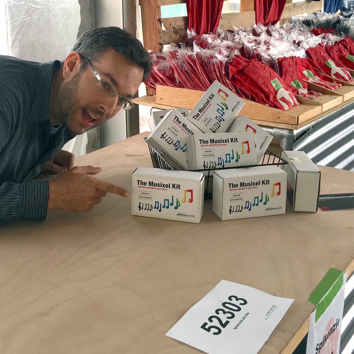
Submitted by Garrett on Thu, 12/10/2015 - 17:03. Super-sized Musixel WallAt the World Maker Faire in New York City this year, we were able to show off the RGB Shades in the Maker Shed for the first time ever! It was a lot of fun, and we were positioned right next to our friends at Spikenzie Labs. They brought some new products, including the Musixel (an audio sensor that controls a strip of addressable LEDs). Here's a quick demo video of what the Musixel kit can do: It's a small PCB with an audio input jack, an 8-pin PIC microcontroller, an MSGEQ7 seven-band spectrum analyzer chip, and various passive components. The PIC reads analog values corresponding to several frequency bands from the audio jack, and outputs WS2811-compatible commands. Spikenzie Labs includes a strip of 16 WS2812 LEDs, but it will work with up to 64 WS2812 LEDs arranged in an 8x8 matrix.
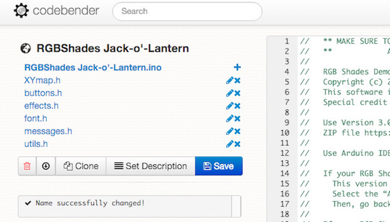
Submitted by Garrett on Sun, 11/08/2015 - 20:17. RGB Shades Jack-o'-LanternHere's a quick demo of how to create a new pattern for the RGB Shades. We'll add some jack-o'-lantern triangle eyes, and make them flicker orange just like the real thing (well, sort of). First off, here's the final result. It's pretty hard to capture the effect on camera, especially since orange colors seem to max out the sensor so that it always appears bright. But watch the reflection in the table and you'll get the idea: We're using codebender to edit and upload a custom sketch to the RGB Shades. Once you get the browser plugin installed, it's a really easy way to get started without a lot of downloading and setup. Plus, all the required libraries are pre-installed and kept up-to-date. In this case, we're using the excellent FastLED library, which controls the WS2812/APA104/Neopixel style LEDs easily and has many helper functions for managing pixels. (A Codebender sketch used to be located here. Sorry, that service was shut down!) Clicking that should display a sketch editing window much like the one below (if you're logged in on codebender): You can clone the project to your own account by pressing the Clone button. Then, change the name to make the project more descriptive by clicking the name of the project and editing the text there.
Submitted by Garrett on Mon, 10/26/2015 - 23:56. LED Shades at Make: Volume 43 Wearables MeetupMake recently held a meetup at their new makerspace located in the Palace of Fine Arts in San Francisco. The theme was the celebration of their new volume of Makezine, Volume 43, the Wearables issue. We wish we could have been there, but were thrilled to see this video of our LED Matrix Shades putting in a major appearance thanks to Tenaya Hurst! Submitted by Garrett on Sat, 01/24/2015 - 01:40. |
Cool Links 
|


Recent Comments
5 years 2 weeks ago
5 years 2 weeks ago
5 years 4 weeks ago
5 years 11 weeks ago
5 years 18 weeks ago
5 years 19 weeks ago
5 years 23 weeks ago
5 years 23 weeks ago
5 years 26 weeks ago
5 years 32 weeks ago