

Buy ProductsDistributors     |
Stealth USB CapsLocker* Source code and Eagle PCB files: CapsLockerPCB&Code.zip * Just in time for April Fool's Day! I built a device that has the potential to drive a computer user insane. This device plugs into a USB port and implements a USB HID keyboard. Instead of doing anything useful, it waits between 30 seconds and 8 minutes and sends the scancode for the Caps Lock key. This will toggle the Caps Lock status on or off. Since the operating system controls the LED on the keyboard, the Caps Lock light also toggles. This makes it appear the user has accidentally pressed the Caps Lock key...until it happens 20 or 30 times and they get suspicious. Then they might see the Caps Lock light turn on by itself. Next is a sequence of reboots, bashing the keyboard on the desk, clicking through the Control Panel, possibly even replacing the keyboard. Unless they notice the tiny little device sitting in one of the USB ports on the back of their computer, nothing will help. Disclaimer: This device provides keyboard input to a computing device outside of user control. It is intended for experimentation and demonstration purposes only. It should never be used in a situation that can result in loss of data, property, or finances. It should never be used in a situation that could cause harm to a person via operation or failure. Usage of this device is beyond my control and I am not responsible for any damages resulting.
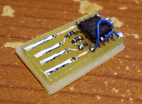
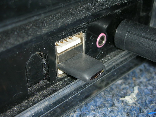
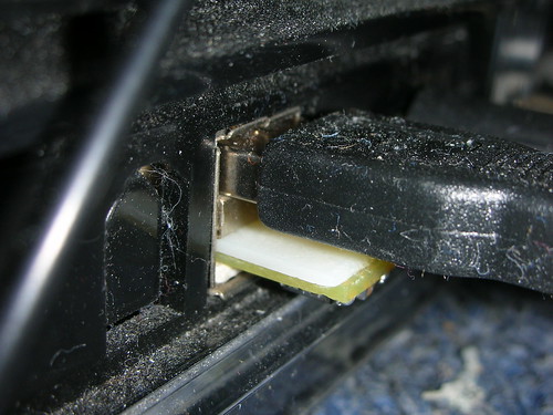
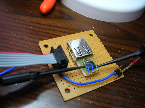
The CapsLocker was built on an Atmel AVR ATTiny45, and heavily based on the EasyLogger application from ObDev. Very little code modification was necessary to get the random Caps Lock activation working. This is a single-sided PCB with a couple of jumper wires for simplicity. If I had decided to use the test clips from the beginning, the jumper wires would be unnecessary. Here are some additional photos showing the installed device and heatshrink over the part that extends from the USB port. Some have commented on the apparently dirtiness/hairyness of my computer. It really doesn't look that bad until you get up close and use a camera flash. That particular computer has been sitting in the same place on the floor for a year or two, so dust does accumulate. It's probably time to find the vacuum cleaner attachment kit. Adapter used for programming the device over ISP:
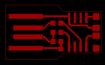
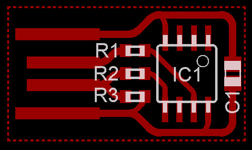
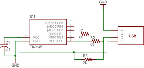
Updates: Since using test clips directly to the ATTiny45 leads was working fine, I modifed the PCB design so that no jumper wires are required. The size remains the same. Here's the new design: And here's the schematic:
The PCB and schematic were created in Cadsoft Eagle. Here is a zip file containing the Eagle project file, schematic, PCB, and a tiled PCB: I've created a tiled set of PCBs. This is handy when using the toner transfer method of etching, or when creating more than one device. Here is a PDF of tiled arrangement, already mirrored so that it is ready to print for toner transfer:
Parts List:
Construction: Print the mirrored PCB on glossy photo paper and trim to the size needed. Iron onto freshly-scoured copper clad until firmly attached. Soak at least 30 minutes in water, then carefully peel off the paper. Fibers will still be attached, rub these off with fingers or a soft toothbrush. Place board in etching solution until all exposed copper is gone. Use solvent such as acetone to scrub off the toner. Use PCB shear or diamond cutoff wheel to cut board to edge of dotted line around PCB. Solder parts onto PCB. It may also help to tin the USB pads, to prevent connection problems due to oxidation. We're not going to be using gold plate, so solder will have to do. Commenter "Stev" says:
Trim piece of plastic to size of PCB and super glue to the bottom side. Important: make sure the plastic shim is wide enough to prevent the PCB from sliding sideways in a USB port...test it. The required thickness of the plastic will also depend on your PCB thickness. The total thickness at the USB connector should be just under 2.0mm or 0.079 inches; trim or sand the plastic to match. Too thick may break the computer's USB connector, too thin may not allow a good connection. Using reference from AVR ISP connector pinouts and the pin names on the schematic, find a way to connect an ISP header to the PCB temporarily. My solution involved a USB jack and two fine-tipped test clips. Other possible solutions may involve a jig with spring pins, kynar wire temporarily soldered to the right locations, or a clip that fits over the SOIC8 on the PCB. All of the above eventually must connect to an AVR ISP header, and this must be connected to a PC through an AVR ISP adapter. These are inexpensive and available from several sources: USBTinyISP, AVRISP, AVR Dragon, and many more Google can tell you about. Download capslocker.hex and use AVR Studio or a standalone programming tool to write into the ATTiny45 Flash. Oh, you'll also need to select the fuse for PLL/1k clock source. If you want to see and/or modify the source code, here it is: CapsLockerPCB&Code.zip The ZIP file above contains the PCB, schematic, and C source code. It is based on the latest version of the EasyLogger code. I've imported everything into an AVR Studio project, but it can be compiled with standard GCC tools that have ATTiny45 support. I have trimmed out the portions of code that were not necessary in this application, and added the modifications required to press the Caps Lock key at random intervals (psuedorandom, the same pattern will occur on every powerup). As the code will make evident, the Objective Development software USB library makes it extremely simple to create a USB device.
Future development: Develop firmware that allows switching between mouse and keyboard, user selectable pools of keypress options, phrases, timing configuration, etc. All controlled via Control reports from an application on a PC. Device would wait for 15 seconds after being plugged in, and begin normal operation if the configuration application did not contact it during the startup time. Now that the Stumblepede is mostly over, I'm going to trim out some of the less-relevant comments below. Your humor was appreciated. :)
Submitted by Garrett on Thu, 04/03/2008 - 16:02. |
Cool Links 
Recent Comments
|
This, my friends, is what
This, my friends, is what the word "awesome" is made for.
*sigh* I could think of
*sigh* I could think of better things to do with my time
could you have it "type"
could you have it "type" something too? How about "I'm watching you...."
i think it should type: "All
i think it should type:
"All work and no play makes Jack a dull boy"
or it culd hit "backspace"
or it culd hit "backspace" at randm so yo miss lettrs
Alt+F4 for the win... it
Alt+F4 for the win... it would be fun randomly closing programs
WIN-R for execute dialog,
WIN-R for execute dialog, then start any program and insert any key sequence - hotkeys or TAB for field selection, SPACE for button press.
I really don't think that
I really don't think that YOU have to worry about mistyping something ;)
They were obviously
They were obviously demonstrating their recommendation by doing that... Kinda went right over your head, huh?
I prefer it to type "redrum"
I prefer it to type "redrum" randomly.
Here, here. The larger the
Here, here. The larger the percentage of other people in the world that fall into this category. The better it is for mankind.
Obviously you can't find
Obviously you can't find better things to do with your time, as you spent the past few minutes reading this article...more than likely trying to convince yourself that you know what the schematics were implying, despite the fact you are as clueless as a 12 year old in a bio-chem lab, and then found the time to even post a comment afterwards....Congratulations on your ignorance and immaturity!
On the other hand, to the matter truly at hand here... Freakin' brilliant idea to start with, and to materialize the concept into a working protype? Wonderful! Hopefully I can find the time in the next few weeks to attempt to build my own to toy with! Thanks so much for this post, and a special thanks for the detail you went into on creation!
Good... Then do it!
Good... Then do it!
WHERE CAN I BUY THIS??? i
WHERE CAN I BUY THIS???
i want one
I m too dumb to build something like this on my own XD
Hi, Garet, I'm very
Hi, Garet,
I'm very interesting for this project, but reason is diferent.
On my job place I have 6 new Fujitsu Siemens computers. Monitors, keyboards and mouses for this computers is in control room, and connected with computers over extenders.
But, for this computers is necessary to have connected keyboard to boot! I dont know why, Fujitsu support answer me that new BIOS version require this.
Your Stealth USB CapsLocker is solution for me, but without capsLocking. How I can do this?
Thanks in advantage,
Predrag
Hi, have You found solution
Hi, have You found solution for Your problem? I'm facing the same thing, temporarily I've removed PCB from keyboard :) It works but it is still too big for me. Your idea is better.
Why not just shut the
Why not just shut the keyboard check off in the bios of the pc? usually this is under boot checks once you entered the bios ( press F keys to get in it. or DEL. its for every system divent..)
Indeed, this is so awesome I
Indeed, this is so awesome I would call it SUPER AWESOME. And for all you morons on irc that like mixed case, this is the tool for you! Just reprogram it for 1-3 seconds!
Agreed. Some people don't
Agreed. Some people don't appriciate a good, friendly joke.
"Super awesome" would you
"Super awesome" would you say that in public? Grow up man. Get out there and live your life. If I may quote Belinda Carlisle "live you life be free, open up your eyes and you will see"
Classic, burning someone
Classic, burning someone with a Belinda Carlisle song, you loser
whoever said this is a
whoever said this is a comp1337 FAG!!!
Oh the stinging irony of
Oh the stinging irony of being told to "grow up" for simply saying a particular phrase, then immediately being told to "'live your life to be free'" If the presence of Belinda Carlisle is any indication, this must be some cutting edge, avant-garde flamebait.
wow, i love reading peoples
wow, i love reading peoples comments. i havnt laughed so hard in a long time reading the "classic, burning someone with a belinda carlisle song..."
Nice hack. BTW, you need a
Nice hack. BTW, you need a vacuum cleaner. :)
ummm schematics and code plz
ummm schematics and code plz I cannot wait to print this board =)
I'll make sure to post them
I'll make sure to post them tomorrow!
CAPS LOCK SWITCHER FTW
CAPS LOCK SWITCHER FTW
hmn, methinks I am about to
hmn, methinks I am about to become annoying on a level that I have never attained before.
work colleagues beware!
This is such an
This is such an awesome/hilarious idea. Can u give us the source code?
THIS IS NOT FUNNY SOMEONE
THIS IS NOT FUNNY SOMEONE DID THIS TO MY COMPUTER AND I CAN'T FIND THE CHIP THAT'S CAUSING IT
I bet its software on the
I bet its software on the computer dumbass
why is your name not in all
why is your name not in all caps then?
I want one.
I want one.
so can you make more and
so can you make more and sell them? i would buy about 10 of these little buggers and place them on the computers at work.
Next, a version for the
Next, a version for the internal USB header, think this one is hard to spot?
Use a CD Rom audio cable and tuck this up above the CD rom drive.
Change the code to a PC mouse HID and flip the scroll wheel or jig the X and Y randomly :D, this is so evil, and at the same time awesome.
Digital Super Glue for pranksters ;)
Or.... why not just steal
Or.... why not just steal the motherboard. Then after about 3 days, they will think "Hey! This is just not working right!" Then you can jump out of the closet and yell "April Fools!" and hand them their motherboard back.
good one!
good one!
it looks like the PCB is 1/2
it looks like the PCB is 1/2 the thickness of the slot, why not make the board double sided (making the whole device remain inside the USB socket) hence it will only be possible to remove with tweezers...
the splinter in the toe of the PC.
--
Conor
This was considered, and it
This was considered, and it totally possible with a double sided PCB and the TSSOP or MLF variants of the microcontroller.
This is precisely the kind
This is precisely the kind of office mischief Thinkgeek adores. You should send this their way, see if they could hook you up with the guys who make the Annoyatron.
It has alreaady been
It has alreaady been done.
http://www.thinkgeek.com/gadgets/electronic/a11e/
man, that is a really cooL
man, that is a really cooL IDEA OH CRAP SOMEONE GOT ME
I HaVe BuILT this BUT I
I HaVe BuILT this BUT I thINK there IS an ISSUe with the INternal CloCK CIrcuit On THE uniT AS it SeeMS TO BE RUnning RANDom BUT WAy Too FasT.
How do we know you aren't
How do we know you aren't just a really slow typist?
Could you make it press
Could you make it press insert?
Ah...good catch. Another
Ah...good catch. Another annoying key I hadn't considered. Yes, it would be very easy. In the current code (posting soon) simply replace 0x39 with 0x49. All the Usage Page 07 keys available are in this document.
"Keyboard Paste," 7D, would
"Keyboard Paste," 7D, would be another good one..
how about the home key?
how about the home key? then in the middle of typing a sentence, BAM its at the beginnning... backspace would also be good.... but capps is awesome... i dont see alt+F4 as a posibility?
what about ALT-CTRL-DEL ?
what about ALT-CTRL-DEL ?
I want one really bad!!!! I
I want one really bad!!!! I will buy one off of you!! It would be cool if you could use the scancode for the escape key or CTRL-ALT-DEL or watever
This is a nice practical
This is a nice practical joke to use cautiously. Employers paying salaries for lost productivity caused by a malicious act could consider it sabotage. This could lead to disciplanary actions, dismissal, or even a law suit. Individuals who lose their precious time or lose valuable resources to a "joke" might sue you. It is funny until someone get hurt by the joke.
I know many persons with limited troubleshooting and computer skills that this prank could push over the edge emotionally. Please use your gifts to better someone's day.
Yes they could commit
Yes they could commit suicide which would be the equivalent of pushing evolutions accelerator if you ask me.
What a rubbish product, idea for use, and forum.
I know! It's great!
I know! It's great!
^^^ Killjoy... This would be
^^^ Killjoy...
This would be a fun plan to play on someone somewhat (some, some, some...) techy, it'll drive them more nuts not being able to fix it.
Garrett, is this the chip
Garrett, is this the chip you used?
Atmel ATtiny45-20SU
Yes, click here for Digikey
Yes, click here for Digikey link.
Thanks, although they're
Thanks, although they're sold out until next month. The only site I could find that had them in stock required a $30 minimum order. Is there an MLF version available that you know of which might be carried by Digikey or Mouser?
Oh, that's strange. When I
Oh, that's strange. When I posted this earlier today, I thought there were about 600 in stock. Maybe that was a different part. These are SOIC anyway, and I'd probably go with the TSSOP in a redesign rather than the MLF. If you don't mind paying a few more cents, the ATTiny85 will also work, it just has twice the Flash storage.
Haha. When I looked
Haha. When I looked yesterday morning there were 1400, so down to 600 by the afternoon and 0 by evening. It looks like this is pretty popular :-)
Thanks for the tip on the 85. I just found some 45s through Newark and was able to tack it on another order. But I might try the 85 later to see what I can do with the code.
Will an tiny45V work as well
Will an tiny45V work as well or does it need to be a 0-20mhz?
I don't actually know. Since
I don't actually know. Since the 45V is rated for 10MHz and we're using the internal PLL to get a system clock of 16.5MHz, I have to assume it either wouldn't work or might be unreliable. Then again it might be perfectly fine. I always get the 20MHz parts anyway.
Garret - Source code??? Can
Garret - Source code??? Can you post or send. Is it in ASM?
I posted the schematic, pcb,
I posted the schematic, pcb, and hex file today...tomorrow I'll post the source code. The AVR-USB package include some assembly files, but the code you interact with will be in C. I find AVR Studio 4 SP2 with the latest WinAVR does really well.
Can you post a complete
Can you post a complete parts list with Digikey part numbers by chance? Thanks!
this is SWEET! its torture
this is SWEET! its torture for sure! My room mate uses a mac, will this still work?
If the Mac uses a USB
If the Mac uses a USB keyboard it should work perfectly. USB keyboards are standard and this is emulating one. :)
That's what I thought
That's what I thought too...but I plugged it into a Mac today and the OS popped up some crazy window saying it can't identify WHICH keyboard I'm using, and to press the key next to the left Shift. Obviously impossible on this device. But this should be a relatively simple fix, either by spoofing an ID of a real keyboard or just pressing Enter then Z for a few seconds :)
This has great potential for
This has great potential for troubleshooting. Can you make one that simulates holding down shift or option (or switchable between both) so I can pop it in, boot the computer and walk away knowing it will boot into safe mode?
There's nothing safe about
There's nothing safe about booting your computer.....minimise the damage by wearing slippers instead of shoes.
Wow. The amount of people
Wow. The amount of people without a sense of humor really disturbs me. I think it's awesome, so long as you're not so cruel to not eventually let your "prey" off the hook.
Talk about ingenuity. This is so beautifully simple, and the fact that you're using a firmware based USB core is also amazing.
Now, to you losers posting your idiocy:
If you can't see the beauty of how simple this little project is, regardless of it's intended use, you're a tech/hack midget.
It's also amazing that a bunch of you morons who can't pull your heads out long enough to see this as potentially, mind you, potentially funny are posting their flame-bait as "Anonymous". Losers post flames as "Anonymous".
We all seem to be singing
We all seem to be singing from the same hymn book Walter, what's your beef? Bad night?
It might be Walter refers to
It might be Walter refers to posts already "trimmed" by Garret. He states "Now that the Stumblepede is mostly over, I'm going to trim out some of the less-relevant comments below. Your humor was appreciated. :)" at the beginning and Walters post is a few days old...
Garret: great project!
I am not a techy and only
I am not a techy and only vaguely understand the technology you're describing, however, I do appreciate the deviousness of this PRACTICAL JOKE(sorry, hit the caps lock, I think). I had a friend who was the sys admin in a professional office. He used a program like Back Orifice and would randomly open a user's cd tray or close a program. He even changed the user's sounds to always play the Close Encounters theme. Yes, practical jokes can be taken too far, techy or not, but it is a bunch of fun watching a nervous breakdown.
hehe.. :)
hehe.. :) Awesome.
Resetting someone's background using keyboard shortcuts or launching particularly colourful web pages comes to mind.
BTW I might have a use for this project, having lost yet another pendrive to USB port flakiness. Watch Hackaday :)
-A
plug it in to the internal
plug it in to the internal usb headers, but solder it onto the back of the mobo, sending random keycodes like:
-Alt+F4
-Alt+Tab
-Win+L
-Win+D
-Win+E
-Ctrl+Z
-Left ALT+left SHIFT+PRINT SCREEN
Thanks for the code
Thanks for the code Garrett!
Bummer, I do ASM & BASCOM, not really C
Also needed to run it on the AtTiny85 ('cause I have them) which only does 8MHz internal RC clock
I may be able to tweak it a bit.......
Your ATTiny85 should have a
Your ATTiny85 should have a fuse you can select for PLL/1k clock source. This will allow the 16.5MHz internal clock generation.
I slapped myself for being
I slapped myself for being so stupid.
The Tiny45 and 85 are in the same datasheet, aye.
I haven't played with varying the clock as ultra-speed has never been needed, other than divide by 8, so something new...
I guess I can measure the exact osc freq by pumping it out the external osc pin temporarily.
Is the HEX file in the code for a 16.5MHz clock??
Or is that HEX file for
Or is that HEX file for 16MHz clock?
Or to get 16.5 MHz do I use the PLL and start playing with the OSCCAL?
I should go home and start playing with this thing...
If you can set the PLL fuse
If you can set the PLL fuse and download the hex file, it should be ready to go. The AVR-USB functions have neat way of using the USB bus clock to calibrate the oscillator automatically.
Hi Garrett I wired it up to
Hi Garrett
I wired it up to a USB socket & programmer, set the PLL clock source, loaded the HEX file but get "USB Device Not Recognised"
Resistors are 47R and 2k2, not exactly the same as yours but what I had.
I enabled ClkOut and measured it as 16.2MHz
Checked wiring against schematic & your PCB layout...
Still no-go :-(
And I turned off the
And I turned off the clkdiv/8 fuse bit too
That information would lead
That information would lead me to believe there is an issue with your USB data lines. 16.2MHz is almost 2% tolerance, the AVR-USB automatic calibration is supposed to get within 1%. Since the calibration is based on the USB frame clock, a signal problem would result in an incorrect clock as well.
Double-check all of your connections, possibly try resistors higher than 68 ohms if you don't have the exact value on hand. I'm also assuming you have the USB connection correct, but please remember the card edge connector will be reversed from the standard USB pin order. I don't know if you tested the oscillator in a USB port or on the bench.
Also, some computers might
Also, some computers might not like a USB high level of more than 3.6V. I removed the zener diodes from the original EasyLogger design to save space, because I used 5V levels all the time and it was never a problem. If necessary we might add those back in.
Measured clock while plugged
Measured clock while plugged into USB port - 16.544MHz
I chucked a couple of 390 ohm in series with the 68 ohm's and "bingo" Found device CapsLocker and HID Keyboard Device is loaded. Just waiting for a CapsLock to happen... OH THERE IT IS!!
HAHAHA Plop. (Yep, laughing my head off)
Dunno what resistors should be, maybe a 2k2/3k3 divider will bring the levels close to 3V?
Thanks Garrett!!
It will not work with all
It will not work with all PC's, because USB D+ & D- will be working around 5V, and they should be 3V3.
So, sometimes it works sometimes it does not
You should add 2 zener diodes between datalines and ground.
check the source off all this here at http://www.fischl.de/usbasp/
That's why the resistor
That's why the resistor sizing is ending up causing most problems for people who don't have 68 ohms. CapsLocker redesign will include zeners, space permitting. Original design was quick and dirty with parts I had available. :)
How difficult would it be to
How difficult would it be to calibrate the oscillator using a parallel port programmer as opposed to an AVR-USB?
That should not be
That should not be necessary. It will auto-calibrate to the USB frame clock every time it is plugged into a USB port.
Just having a chuckle to
Just having a chuckle to myself...
How about a random Tyrrets version
Ha ha f'ing ha
Did you program it through
Did you program it through the usb header - i.e. only connecting to reset and pin 6 by clip? I'm wondering if the 2k resistor (or the two 68s for that matter) will affect the programming?
Programming works just fine
Programming works just fine with the resistors in place. At least with the programmer I'm using right now (ISP from an STK500).
Indeed 2k fouled my cheap
Indeed 2k fouled my cheap STK200/300 compatible programmer - just a 74hc244 ON THE LAPTOP PARALLEL PORT. CapsLocker strikes again... I have a 4k7 betweek pins 1 & 2 of the USB plug which saved disconnecting the resistor during programming. EPROM and Fuses programmed using "BasCom-AVR" software. Don't forget to enable PLL and turn off ClockDiv/8.
I'm currently building one
I'm currently building one of these inside a usb connector although I dont have any AVR parts yet and they seem really hard to get hold of in the UK. I took a scalpel to the outer plastic down one of the seams and cut off the strain relief part so the metal shell slid out. It then opens like a shield can with two little clips and I yanked out all the cables. As it happens, the white plastic piece left perfectly accepts the copper wire from 5A (I think) twin and earth mains cable to form the pins.
I've soldered the cap on the ground pin and the 2k between pin 1 and 2, and added two surface mount 68 ohm resistors to the usb pins. They seem to hold perfectly in place. I've then added kynar wire between the cap and vcc. My intention is to solder the avr upside down with its legs facing the pins (90 degrees from how you have it) and tack 4 lengths of kynar on to the pins to connect it up. I can then fill it with hot melt glue and replace the other half of the shield . I may even solder the shield closed.
I'm considering an interesting programming option though - potentially I could connect one programming pin to the shield. This is floating in a usb socket but it seems all actual usb ports connect it to ground. Thus on the programming board, the shield could be wired up to program with. That leaves one pin to deal with that I'm considering could be a small screw eye from a diy store with a bit of heatshrink covering it and glued in place of the usb cable. That would effectively give a keyring holder and the final programming point :-)
Ok. I can't think of a
Ok. I can't think of a reason off the top of my head why this won't work, so maybe someone can verify for me.
What if I were to solder a 2-position surface mount dip switch between the Vcc rail and pins 2 and 3. Couldn't we then Modify the code to read a value from the two ADC lines and switch the keyboard output by flipping switches instead of reprogramming?
That's how the EasyLogger
That's how the EasyLogger does it. Really, they figured out how to do internal RC with USB because they wanted to make more I/O available...I'm just using it because I want the device to be as small as possible, I don't need all the I/O.
But an external switch won't be necessary with the upcoming new firmware and the configuration app. You'll be able to tweak everything and the settings will be written to EEPROM. I would say...one or two weeks away, have too much else going on right now.
I would sh*t myself with
I would sh*t myself with fear if I found that thing sticking out of my USB drive, wipe my HDs, burn the entire contents of my filing cabinet, and probably flee the country.
You made me laugh
You made me laugh
You do realise that this is
You do realise that this is kind of like posting something like a newspaper that no one will notice and set off a firecracker to scare someone when they walk by.truly hilarious until you get dissapeared by the government because some douchebag sticks a bomb in it. sometime soon some jackass is going to load an identity theft or some other kind of vicious program on one of these and YOU are going to be blamed. it really sucks that this is probably going to be the situation, but you should probably post a disclaimer of some sort. BTW ive already made a couple that switches the caps lock key on and off by 50,000 divided by the fiobinacci sequence. every time it switches the caps lock on and off it goes to the next term in the fiobinacci sequence, increasing the frequency. ;) happy trails and be safe in this world of fear mongering and control
Unfortunately, it already
Unfortunately, it already has been done, a long time before this was posted. There was a bank robbery attempt using a stealth keylogger/remote controller plugged on an office computer's USB port (here, in France). And the device was kinda the same.
This is really cool. I am
This is really cool. I am trying to get into AVR microcontrollers, and to learn how to program too. I'm still a beginner though. I already have a programmer though. http://ladyada.net/make/usbtinyisp/index.html
I'd like to attempt to make one of these. Mainly for learning purposes.
First, I'd like to know what AVR's I should buy. I'd like to try this with DIP style type first, as I've never worked with surface mount devices, and not much electronics in general.
I was thinking of either ATtiny45V-10PU or ATtiny45-20PU. I'm not sure whether the 10 mhz or 20 mhz is needed. I don't think it matters, since you set the fuses, but i have no idea. Would either the ATtiny85V-10PU or ATtiny85-20PU work too?
Second, I'd like some sort of help with how to set the fuses. I've never done it before. I'm using avrdude if that helps. Any help is appreciated. Thanks.
If you guys want to really
If you guys want to really start ballin with the big dogs, you should check out the MSP430, but that kinda takes some serious education and development tools to implement. It's kinda worth it though, I took a course at the local tech school to use it and the thing is crazy its just like "oh hey, i do absolutely everything you could ever want a microcontroller to do, oh and by the way there are like 20 million variartions of me for almost every kind of specialized task" downside, they are like $11+ just for a standalone chip, generally about 80 pins, and only come in SOIC
"ballin with the big dogs"
"ballin with the big dogs" Pathetic! absolutely pathetic.
You could also make it open
You could also make it open the cd drive over and over
if you load the data onto a normal flash drive and use the auto play, will that work also?
if you are just going to use
if you are just going to use a flash drive /w autorun, then just make a simple autoit script. CDTray("F:","open") the beauty of this caps lock device is that it is cheap, and hard to detect. besides most corporations disable autorun on there computers
Sony actually makes a usb
Sony actually makes a usb storage device this small and it would be helpful for those of us whose small motor skills are hampered by disability. I can code, but I can't assemble something that small and I can afford to pay the larger price for the Sony usb device. See them here: http://www.sony.net/Products/Media/Microvault/usm-h.html
I just started putting mine
I just started putting mine together and wanted to add to your section on etching & soldering. If you coat the PCB with a clear Acrylic spray paint after removing the toner it will act as a sealant to protect the copper from oxidation. You'll still need to tin the USB connection pins, but the other traces will be protected. It will also act as a flux to prevent solder crossover to adjacent pins.
I just completed my first
I just completed my first Capslocker! Woo!
But whenever I plug it into a USB slot it says USB device not recognized, and that pops up about once every 5 seconds.
I've checked the Write operation, and it verifies correctly. I can also read the program back from the chip. The only thing I'm not sure about are the security bit settings. This is what I have on there right now.
CKDIV8, SUT0, CKSEL3, 2, 1, SPIEN
Are these correct? Any any ideas what could be causing it?
For reference, I'm using PonyProg with a DT-006 parallel port programmer.
Hi Stev (& Jacques) I
Hi Stev (& Jacques)
I changed the 68R's for 390R to help with 3.3V compatability (yep parts from the junk box, after Garrets suggestion of increasing the value, voltage divider may be better but bigger!) and then the device is recognised as CapsLocker then HID Device. Works now! I found some 300R SMD resistors for the final build and they too worked. And... I changed the 2k2 for a 4k7 as the 2k2 stopped my parallel port programmer from working.
Sorry, not familiar with ponyprog but see my other posts on fuse bits.
See if this makes sense:
FuseBit H = 1 (disable div/8)
Fusebit FEDCBA = 100001 (CKSEL=0001, SUT=10)
Cheers,
JT
Thanks JT. Those fuses are
Thanks JT. Those fuses are what I tried to set in PonyProg, but as soon as I write the disable div/8 it goes crazy. The support in PonyProg for ATTiny45/85 is in beta though, so that's probably why. I just didn't know of any other windows-based programmer that supported the DT-006 parallel interface.
Once the AVR Dragon comes in I'll use HV programming to reset the chips and try again with AVR Studio. I'm also going to see if Fry's has any 300? SMDs for once my new chips come in.
Hi Stev For Windows users,
Hi Stev
For Windows users, Dontronics web site mentions that the DT-006 is compatible with Bascom-AVR...
You can download the demo from www.mcselec.com and it works fuly, only with a compiled code limit of 4kb. I don't know if the programmer side has this limit but the CapsLocker HEX file is below it. Just select your programmer type in the options (I use STK200/300 compatible), click on Manual Program, load the HEX into the programmer buffer, write it, and set 2 fuse bits options, done.
Cheers,
JT.
Does anyone have any good
Does anyone have any good suggestions for a programmer to use? Preferably something less than $40. thanks
Usbtiny from
Usbtiny from http://ladyada.net/make/usbtinyisp
its like 22 bucks
I got a couple of cheap 70
I got a couple of cheap 70 cent USB cables from monoprice, and cut off the ends. I used that in place of making my own connector. i know it costs a little more, but it saves some aggravation in the end.
Hi Anonymous ;-) Cutting
Hi Anonymous ;-)
Cutting open the USB connector is fairly easy, nowhere near as small as Garrett's PCB version but works fine. I used the DIP8 AVR package which doesn't quite fit inside the metal shield of the salvaged USB connector but using SMD resistors pinched form other PCB's... makes it fit inside the plastic. I haven't made PCB's for years.
It has still been easy to 'hide' in USB ports on the back of PC's and still heaps of laughs.
Cheers,
JT.
the dust is driving me mad!
the dust is driving me mad!
nice design - compared to
nice design - compared to the us-geek thing
http://www.thinkgeek.com/gadgets/electronic/a11e/
how do u actually load the
how do u actually load the software onto it?
put a adapter and connect it to the comp?
or straight from the circuit/
would someone be willing to
would someone be willing to make and sell these. I will order a few if they are reasonably priced. Or is there already somewhere to buy it pre-made?
Will it work on a MAC!!???
Will it work on a MAC!!???
How soon can we get one, or
How soon can we get one, or a kit, from Make Magazine's store or Thinkgeek?
They have just been picked
They have just been picked up by an international publisher, and will be out soon on a monthly basis. You will get a free binder with part 1, and in 12 months you'll have your idiotic fob.... No you won't because. The mantra has remained unchanged for years - free binder with part one, part two free with part one, part three rarely sees the light of day, end of story. The fools used to call them 'partworks', but come off it. They were 'bindermags', pure and simple. Wake up and smell the coffee as I believe you chaps say over there.
It SHOULD work on a mac,
It SHOULD work on a mac, since it is displayed as a generic keyboard. But, who knows for sure.
..and for a nice cheap $20 programmer check here:
http://ladyada.net/make/usbtinyisp/index.html
or
http://www.adafruit.com/index.php?main_page=product_info&cPath=16&produc...
P.S. I still need help selecting a DIP chip, and need help with fuses. Please help.
Hi Andrew Get the Tiny85
Hi Andrew
Get the Tiny85 chips as there's more RAM & EPROM to run your other programs... and probably don't cost too much more than the Tiny45, and are otherwise the same. The DIP8 is still fairly small and good to start off with. About the Fuses... not too tricky to but depends on your programmer software. I am familiar with Bascom-AVR Demo can be downloaded from http://www.mcselec.com which has easily selectable fuse options from drop-down lists. For this application you need to enable the PLL clock source, and disable the "Clock Division by 8". These are not the default options programmed into the chips as shipped.
JT
C1 location on the PCB must
C1 location on the PCB must be before VCC goes to pin 8, not after it! While electrical connection is the same, there is a difference in terms of noise immunity.
You're technically correct
You're technically correct here. However, due to the small size of the IC, the trace length is very short and will really not make that much of a difference...compared to, say, if the capacitor was located inches downstream of the IC power pin and trace characteristics came into play. Mainly I was focused on keeping this a single-sided design and made a few compromises. The double-sided redesign will include more traditional approaches.
lots of dust.
lots of dust.
Thanks JT, That help
Thanks JT,
That help ALOT.
The programmer software I've been using is Avrdude. I will ask around a bit, and see if I can get info for it specifically for avrdude. If not, I'll look into the program you suggested.
Thanks,
-Andrew
(keen101)
pwnage !!!
pwnage !!!
Nasty, very nasty. I must
Nasty, very nasty. I must get one.
now that is luscious! that
now that is luscious! that will drive anyone freakin insane. nice work.
How do you get the 3V for
How do you get the 3V for usb DATA from the 5V from VUSB ?
this wont work with all USB chips
a resistor is a good start
a resistor is a good start
I want to make one of these
I want to make one of these for my old mac G4 so I can have it boot into target disk mode with out a keyboard on it. I am curious if the mac is going to make and annoying noise to have it just hold Ctl+t after it has been booted. This might make my old G4 really useful again.
For those of you looking for
For those of you looking for cheap programmers, a parallel port adapter with PonyProg won't work. As soon as I try to uncheck clock/8 the program somehow flips all lock bits and disables the reset pin.
I finally gave up and order an AVR Dragon. That should keep me busy with plenty of AVRs.
In the recent past I've used
In the recent past I've used a simple parallel port programmer with avrxtool command-line programmer software from Elm-chan: http://elm-chan.org/works/avrx/report_e.html
It worked pretty well. Fuses and everything are done from a command prompt. I set up the programmer so that I could drag a hex file into the shortcut and it would program the device.
But now, AVR Studio supports the newer ATTiny chips, and I have an STK500 which I use with a USB-RS232 converter.
For those of you looking for
For those of you looking for a cheap programmer, a par port programmer will do fine. There are a bunch of designs that include a 74HCxxx buffer chip, but even that is unneccesary. As long as you're very careful the circuit is not connected to anything else, you probably won't blow up your parport.
Programming real stuff becomes annoying during development though: Programming is kind of slow, and cannot be done safely with the target circuit "live". So I finally gave up and built my own stk500V2 compatible programmer.
(according to the captch, though, I'm not sentient... 2 times so far...)
Hello! Would it be possible
Hello!
Would it be possible to BUY one of these from you guys?
Frankly, I have no idea how to do any of this stuff, but I'd really like one of these.
Hello, I have build your
Hello,
I have build your device, too bad it does'nt work :(
I've used 68R and the 2K as in your schematic, programmed my attiny45 with bascom avr and set the fuse's to Divide/8 off and 10001 pll 1K.
I use an attiny 45 20PU (dip) tried your hex file and the one of easylogger.
Please ensure the USB
Please ensure the USB connections are correct. Remember this is a top-side-only layout, and the board is flipped over to put in a USB port, so the USB contacts are mirrored.
Hah! Excellent!
Hah!
Excellent!
Alright! I just got my AVR
Alright! I just got my AVR Dragon in. Set some fuses and and it works! Haha, awesome idea and implementation. I can't wait to mess around with the programming.
Oh, for what it's worth I have 68? resistors and it works in every computer I've tried so far (~5). I'm going to try and pick up some 300s just in case though.
I AGREE, CAN WE PURCHASE ONE
I AGREE, CAN WE PURCHASE ONE OF THESE OFF YOU?
Simply brilliant!!
dress it up like large
dress it up like large capacitor, plug into internal USB ... have fun watching your favorite moron go bonkers
GRRRRREEEEAAAATTTT
:OD I want mine!! can
:OD
I want mine!! can someone sell one on ebay??
Are the resistors
Are the resistors necessary?
Ive got it just wired up to a USB port and... Nothing
I dont have the resistors.
I dont check here often, so if you could email me plz...
And also, are multiple
And also, are multiple keypresses possible?
Ill make this my login key for school.!
Nice. Wonder how hard it
Nice. Wonder how hard it would be to adapt for a PIC? (I have no Amtel experience)
Do you have a USB-Lib for
Do you have a USB-Lib for PICs as obDev.at has made for ATMEL? ;)
I have a question on the
I have a question on the source code. I've been playing around with it and modified buildReport as follows.
static void buildReport(void)
{
uchar mod = 0;
uchar key = 0;
KeyPress = rand() % 2;
if(reportCount == 0 && KeyPress == 0){
mod = 0;
key = 0x04;}
if(reportCount == 0 && KeyPress == 1){
mod = 0xE1;
key = 0x04;}
reportCount++;
reportBuffer[0] = mod; /* modifiers */
reportBuffer[1] = key;}
If I use 0xE2 as a mod key I can simulate an Alt-Tab, but if I use E1 or E5 to try and simulate the shift key nothing happens. Is there any particular reason it wouldn't work?
How do you set the fuse bits
How do you set the fuse bits in WinAVR?
I got it working!!!! Big
I got it working!!!!
Big Thanks to JT!
I successfully made a DIP circuit using an ATTINY85-20PU.
The hardest part was figuring out the fuses with avrdude.
but, the avr calculator helped me out.
http://palmavr.sourceforge.net/cgi-bin/fc.cgi?P_PREV=ATtiny85&P=ATtiny85...
anyway... I figured out the fuses. (thanks to JT's suggestion to "disable the Clock Division by 8 feature)
The correct values are:
avrdude -c usbtiny -p t85 -U lfuse:w:0xc1:m -U hfuse:w:0xDF:m -U efuse:w:0xFF:m
-Andrew
(keen101)
How did you set the fuse
How did you set the fuse bits?
I really loved the term
I really loved the term "stumblepede" :)
Googled for it, and seems like you just migth be the inventor of a new word...
i have a little problem, the
i have a little problem, the device is not recognised when plugged before the PC is powered, it goes into a loop of connect and disconect.
I think it is because it does not manage the suspend mode ...
lol, see, don't ask him to
lol, see, don't ask him to make the Alt-F4 or app closing etc etc, just program it urself ^_^ its not that hard ppl
nice project indeed. I don't
nice project indeed. I don't know well the AVR familly, but how do you connect to the USB with a uC which does not include a USB transceiver ?
Hello. I made the device, as
Hello. I made the device, as described in your article. Payment is not made. All posted on the circuit board.
My device:
http://radikal.ru/F/i017.radikal.ru/0805/d3/3a167d8628f9.jpg.html
http://radikal.ru/F/i008.radikal.ru/0805/ad/0d10bec5203e.jpg.html
Uploaded firmware in Microcontroller. Insert the device in a computer's USB port. And the device is not defined. I even tried to change Microcontroller - that does not work. Errors in the scheme no. All collected as you. HEX file downloaded to your page. I do AVR microcontrollers already 3 years. But only write in Assembly, so check your code I can not. I hope for your help.
Write to me mura-vey@mail.ru
All right. The device
All right. The device worked. The problem was incorrectly installed fuse-bits.
HOW DO YOU DO FUSE
HOW DO YOU DO FUSE BITS!??!?!
what program do you use for
what program do you use for programming chips?
^ asking the person ahead of
^ asking the person ahead of me.
Hehe, This is awesome! Hows
Hehe,
This is awesome!
Hows about Ctrl + Alt + Del,
or Alt + Tab,
Or anything!!!
I am confused as to how you
I am confused as to how you program the chip. Is it possable that you can put up some detailed instructions??
If you are using avrdude,
If you are using avrdude, and a USBtiny programmer to program your chip, then this is how you set the fuse bits.
avrdude -c usbtiny -p t85 -U lfuse:w:0xc1:m -U hfuse:w:0xDF:m -U efuse:w:0xFF:m
http://www.ladyada.net/make/usbtinyisp/
http://www.ladyada.net/learn/avr/avrdude.html
Could you please post the
Could you please post the schematics for the adapter? Also are we allowed to make and sell these? (do you require a cut of the profits or something if we do?)
I don't have a schematic for
I don't have a schematic for the adapter...basically, it's a USB connector to provide ISP power and ground and two other pins. The remaining two pins are connected with test clips, or feel free to figure out some other neat solution.I don't care if someone wants to make and sell this...the code is mostly not mine anyway. Maybe in a month or two I'll refine the design and code and put some up for sale :)
Hello, i thought of soo many
Hello,
i thought of soo many kewl and fun tricks i could do with this device, so i bought all of the parts needed to through it together and i have made the device, i ordered the programmer and got it, now... how do i hook this to the programmer to program it? im pretty new to this(first time) and i really have no clue. if someone could help me out with how to get the programming done i would greatly appreciate it and possibly pay you for your time. feel free to email me at rubymaster3000+had@gmail.com i am a programmer and i know many languages from basic - asm. i just dont know much about compiling and putting the code onto the chip.
thanks
frank
pretty much i dont know what
pretty much i dont know what pins on the chip goto what pins on the programmer....
hmmm i was just wondering
hmmm i was just wondering would either of these work? if not why is it that they wont? im just trying to learn all that i can. thanks
http://i279.photobucket.com/albums/kk140/franklinjlj/work.jpg
Reminds me of an old Amiga
Reminds me of an old Amiga program I wrote that hooked into the global input handler and would gradually start eating mouse-right and mouse-down events, to simulate the way a dirty mouse ball would tend to move more in one direction than the other. It was infuriating.
If your computer's USB
If your computer's USB cannot handle the 5V on the data lines, you can use an LED between the power line and the power pin. This works well on my laptop and is easier to implement than 2 diodes.
When i print this with
When i print this with eagle...do i select to mirror it?
It's a top side surface
It's a top side surface mount board, so no.
This is a cool project. It
This is a cool project.
It does not work with my laptop (IBM Thinkpad T60). Damn IBM.
Works great with my desktop.
Unfortunately, all of my nearby co-workers use these laptops.
You might try the solution
You might try the solution that uses a diode in series with the ATTiny to drop the output voltage a little. Or place 3.3V zeners in parallel to the data lines.
That did the trick! I
That did the trick!
I couldn't find any zener diodes in the house, so I put a red LED inline (between the USB power line and the power pin 8). That dropped the power enough to make the laptop happy.
Works like a charm. Thanks.
I successfully built the
I successfully built the project! Thanks a lot!
I was thinking of changing the key from capslock to using the windows-key + L to lock a windows pc. Any thoughts on how to change the code to be able to use a combination of keys? (also useful for people wanting to create the ALT+F4 or CTRL+ALT+DEL versions)
Heh, Reminds me of a prank I
Heh, Reminds me of a prank I pulled one time. I was working as a debug tech, and I had a bench back to back with another tech, I reached under the bench and plugged a USB keyboard and mouse into his PC. I started hitting random keystrokes every now and again when I heard him typing, Then when he'd turn his back I'd hit the windows key or alt+F4. When he was trying to use his mouse I'd move mine around slightly to give him a case of "Drunk Mouse" He got really upset. But it was all in good fun. After a while he thought it was a pretty good prank.
I'd also like to mention I'd
I'd also like to mention I'd love to buy a couple of these if the price was right.
I have just rebuilt this
I have just rebuilt this with a PIC10F200... It only sticks out of the USB port by 8mm !!
I have also added a buzzer to the circuit, so i can randomly make it go beep. lol
Thanks for the idea! ;)
How did it turn out with a
How did it turn out with a PIC10F200?
I would love to see your source code and any changes you made to the schematic
I did it! Boy did I lEARN A
I did it!
Boy did I lEARN A LOT ... haha! that was the device turning on the caps lock.
Anyway, I copied everything that I could make out from your images. I made my boards from your image, used the SMD components and even figured out how to make your target board.
Now I'm beginning to learn avrdude... the fuses scare me but that link to the AVR Fuse Calculator is excellent.
ThANKS AGAIN! -- hehe, yeah, the device again.
Device Not recongized When I
Device Not recongized
When I plug this into my desktop, I getting the "USB Device Not recongized" popup warning. Any Ideas ... I'm running XP
Could be anything from
Could be anything from soldering errors, to wrongly-programmed fuses. If you don't know what I mean by fuses, that's probably it. Search this page for fuses and you'll find the correct settings.
I'm having the same issue on
I'm having the same issue on some computers. Looking at the previous posts, I'm wondering if the data lines need to be dropped to 3.3V using the Zener diodes. I'm going to build another unit tonight and add those diodes and try it in another computer. I have to build another one because the one I built last night has already been deployed... ;)
Thanks, for the ideas... can
Thanks, for the ideas... can someone send me there fuse setting
CKSEL0 -1 CKSEL1 -0 CKSEL2
CKSEL0 -1
CKSEL1 -0
CKSEL2 -0
CKSEL3 -0
SUT0 -1
SUTO1 -0
CKDIV8 -1
Hi guys. I have problem with
Hi guys. I have problem with this device. It works fine (ATtinny85-20, zene diodes are placed), but after reseting (powerup too) my computer Windows XP does not recognized CAPSLOCKER. I do same test on three different systems, but result is same.
Any ideas?
Great idea. Got it to work
Great idea.
Got it to work after a couple days.
I recommend changing your parts list that people are buying parts from because the 68 ohm resistors dont quite cut it on a lot of computers.
I'm using some 470s I had laying around and they've worked on every computer I've tried it on so far.
Good to know...it might also
Good to know...it might also be related to the 5V signaling that is solved with zeners or a series diode. But changing the resistors is a lot easier....
If any of you successfully
If any of you successfully built this project, then i am going to bet you are going to love this project which is basically the same code and same parts list. But, you put it inside an old NES or SNES controller. I was surprised that the same exact parts (and code practically) were used in a SNES to USB converter. Awesome!!
http://hobbyelektronik.org/wiki/index.php?title=SNES-Joypad
it's in German though. I successfully used Google translate to dis-cipher enough to build it. http://translate.google.com/translate?u=http%3A%2F%2Fhobbyelektronik.org...
can this be used as a 1 key
can this be used as a 1 key keyboard with the f8 code of keboard entered and activated with a external switch
here's a 1 key keyboard
here's a 1 key keyboard project which is very similar to this project. You just need to change the line of code with the scancode to the f8 key and you're done!!
http://blog.flipwork.nl/?x=entry:entry081009-142605
how about setting it so it
how about setting it so it does windows key + m to minimise all open programs, that would anoy the hel out of me.
Thanks for the idea, working
Thanks for the idea, working great today ;-)
Did you ever get to the
Did you ever get to the point of selling these? I'm just not a builder with really small stuff. What a riot.
Thanks for the info on this.
Thanks for the info on this. It got me into building circuit so I could build it.
Hi all, I've built a
Hi all,
I've built a CapsLocker too, and would like to have it send a sequence of keystrokes instead of just one single key.
No matter what I try I end up having the device send at most a combination of two simultaneous keystrokes..
I'm a total noob with C, but can write code in python and basic. ;)
What is needed to have this marvelous little toy send, say, "hello world" instead of just "nothing+capsLock"?
Any help appreciated.